COMSOL Multiphysics uses a global Cartesian coordinate system by default to specify material properties, loads, and constraints in all physics interfaces and on all geometric entity levels (points, edges, boundaries, and domains). In boundary conditions and fluid domains, the global system is generally interpreted as having fixed axis directions in space; that is, it is a spatial frame system. When specifying properties of solid materials, the global system axes are instead fixed in the material. In other words, it is a material frame system in that context.
Not only the global coordinate system, but also coordinate systems defined as a rotation relative to the global system, are context-dependent in this way. Such systems are collectively referred to as relative coordinate systems, to distinguish them from absolute coordinate systems.
In 3D, an image displays in the lower-left corner of the Graphics window  to indicate the orientation of the global coordinate system.
User-defined coordinate systems can be used on all geometric entity levels to simplify the modeling process. In the physics interfaces, you can use these coordinate systems to define orthotropic and anisotropic material properties that are not aligned with the global Cartesian coordinate system. To choose a coordinate system, select it from the Coordinate system list in the Coordinate System Selection section. The list contains the Global coordinate system (the default) and any other coordinate systems that you have added, for example see Figure 5-3. 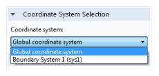
Figure 5-3: An example of options available in the Coordinate system list. The default is the Global coordinate system.
See Table 5-17 for an overview of the available coordinate systems. Note in particular that some coordinate systems specify absolute directions in space, while others specify a rotation relative to the default global system, as indicated by the Type column in the table.
|
•
|
|
•
|
|
|
|||
|
|
|||
|
|
|||
|
|
|||
|
|
|||
|
|
|||
|
|
|
|