When the automatic geometry analysis fails, it is possible to instead specify the stretching directions in each domain manually. First, select the number of stretching directions: one, two, or three. Then for each stretching direction, enter a scalar function of position, di(x), defined such that it measures the distance from the inner scaling domain boundary in the given stretching direction. Also enter the maximum distance for each direction, dMax,i — effectively the thickness of the scaling domain in the given direction.
Stretching functions, fi(ξ), are evaluated as functions of the dimensionless distance ξi = di(x)/dMax,i. The result is interpreted as a stretched distance in the given stretching direction. Finally, the change in distance is multiplied with the stretching direction unit vector, which is computed as the gradient of the corresponding distance function, to produce a stretching displacement relative to the original position. This is done for each stretching direction separately such that the scaled coordinate vector x’ is
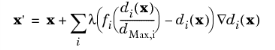
where λ is a typical wavelength.