After a Component node is added to the model, the Geometry ribbon toolbar (Windows) or the Geometry contextual toolbar (Mac and Linux) is made accessible (Geometry Toolbar). Click the Geometry toolbar to display the options.
|
|
Geometric Primitives and Geometry Operations for example, can be added using these toolbars. You can also right-click The Geometry Node in the Model Builder and select any one of the available options. You can also use some drawing tools as listed in Geometry Drawing Toolbar Buttons.
|
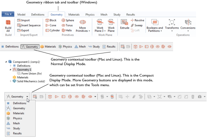
Options become available based on where in the geometry you are working. As in Figure 7-1, the Geometry toolbar has some options grayed out because these are not yet available. As a geometry sequence is built, and you select geometry objects in the Graphics window, the applicable options become available.
When one of the buttons is clicked, COMSOL Multiphysics performs the associated operation on the selected objects and creates the resulting objects, often adding a node to the geometry sequence. If you want to modify the operation, you can edit and rebuild this node. See About Highlighted Geometric Entities in the Graphics Window for details.
In 2D and 1D, there are buttons for drawing Geometric Primitives using the mouse. In 3D, the buttons are available to create primitives, but you cannot draw these using the mouse. See Geometry Toolbar and Table 2-8 for a list of the buttons and links to the individual features.
For Windows users, the COMSOL Desktop displays the current x and y coordinates at the bottom of the desktop when you move the cursor in the Graphics window when working with the geometry. Also, when you interactively create 2D geometric primitives, the display shows the current dimensions for the following geometric primitives:
|
•
|
Rectangle: The width and height; for example. w=3.345, h=2.335
|
|
•
|
|
•
|
Circle: The radius; for example, r=1.352
|
|
•
|
Ellipse: The semiaxes; for example, a=3.525, b=5.134
|
If you do not want to display this information, you can clear the Show mouse coordinates when drawing check box on the Graphics and Plot Windows page in the Preferences dialog box.
For 2D geometries, you can click the Edit button ( ) in the Graphics window’s toolbar to enter an Edit selection mode, where you can perform the following actions:
|
•
|
Click to select; then click- and-drag using one of the small squares in the frame that surrounds the selected objects to scale it. If the scaling is isotropic so that the geometry object retains its original shape and type, the geometry object’s settings show the resulting size and position. If the scaling is anisotropic (stretching a square so that it becomes a rectangle, for example), a Scale node appears under the geometry objects’ nodes in the geometry sequence, and it contains the corresponding anisotropic scale factors.
|
|
•
|
Alt-click to enter a mode where you can edit the geometry object by clicking-and-dragging control points in the Graphics window. Right-click to exit this mode; an Edit Object node then appears under the geometry objects’ nodes in the geometry sequence, and it contains the properties of the edited object. See Editing 2D Geometry Objects below.
|
Use the Edit Object ( ) node to adjust the edges and vertices for a 2D geometry object or to add or delete edges and vertices in the object. In the Model Builder, right-click a 2D Geometry and select Edit Object.
The Edit Object function can also be started using the Edit Object button ( ) in the Geometry toolbar:
|
1
|
|
2
|
Select a single geometry object in the Graphics window.
|
|
3
|
Click the Edit Object button (
|
|
4
|
Use the mouse to drag vertices and control points to new locations. The image is updated in the Graphics window to show the effect on the object being edited.
|
|
5
|
Right-click to exit the object editing mode and save the changes. A new Edit Object node is added in the Model Builder. Alternatively, if the object being edited is an Edit Object feature, the changes are incorporated in the existing feature and no new node is added in the Model Builder.
|
Another way to edit a geometry object, if you are in the Edit selection mode, is to hold down the Alt key and left-click on the object in the Graphics window. This is equivalent to selecting the object and then using the Edit Object toolbar button.
|
|
See Edit Object for details.
|