To unite the geometry, COMSOL Multiphysics evaluates the geometry sequence from the top down. The final node in the geometry sequence (before any virtual operations, if present), the Form Union/Assembly node, determines how to form the geometry that is used for meshing and analysis (possibly after also applying virtual operations). There are two methods to form the geometry, which also determine the name of the node: Form Union or Form Assembly ( ). There are some differences and aspects to consider when choosing a method:
|
•
|
The default method is to form a union. The software then forms a union from all geometry objects that the geometry sequence contains or creates. The union is divided into domains separated by boundaries according to the participating geometry objects. You can mesh the entire geometry and model the physics by assigning material properties, boundary conditions, and other data for the model. It is also possible but often not necessary to specify boundary conditions on interior boundaries between domains in the geometry. By default, COMSOL Multiphysics ensures continuity in the physics interface fields across interior boundaries. See also Removing Interior Boundaries.
|
|
•
|
The alternative method is to form an assembly. The software then treats the geometry as a collection of the geometry objects instead of uniting them. This means that you must use pairs to connect boundaries where a field is continuous, but it also makes is possible to use special pair conditions for applications such as contact modeling, where you can add contact pairs to model contact between geometric parts (requires the Structural Mechanics Module or the MEMS Module). Forming an assembly is also required to model geometry domains that slide or move relative to each other. By default, identity pairs are created automatically when forming an assembly. An assembly can also be useful for meshing each geometry object independently in, for example, thin and slender geometries with high aspect ratios. Another case where you need to use an assembly is when the geometry is too complex for forming a union, which might be the case when importing an assembly geometry from CAD data.
|
|
|
The Form Union/Assembly node ( ) ends each geometry sequence in 1D. In 2D and 3D, it is possible to add virtual operation nodes, some partitioning nodes, and selection nodes after that node. In the Model Tree, its label is Form Union or Form Assembly depending on its settings. By default, it unites all geometry objects into a single geometry object (this is the Form Union variant). You cannot delete or disable the Form Union/Assembly node. When you leave the geometry sequence to define materials or physics nodes, the Messages window provides information about the method (forming a union or an assembly) and about the number of geometric entities (domain, boundaries, and so on) in the geometry.
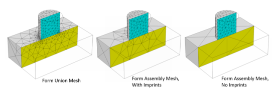
The default method, Form a union, forms a union of all geometry objects. Select Form an assembly from the Action list if you do not want the geometry objects to be united. The program then forms the geometry by collecting the objects in an assembly object. If you form an assembly, select the Create imprints check box to get imprints of the geometry objects that touch each other. An imprint of a usually smaller object’s boundary on an adjacent larger object’s boundary inserts points on the boundary in 2D and creates edges on the boundary in 3D. Creating imprints can be useful when you need identical matching meshes on both objects’ boundaries or when you want to split the larger boundary so that it contains a segment or area that matches the smaller boundary. Select the Create pairs check box (selected by default) to generate pairs corresponding to the objects that touch each other. Select the Split disconnected pairs check box to generate one pair for each connected set of boundaries. Clear the Split disconnected pairs check box to generate one pair for each pair of objects that touch each other. From the Pair type list, select Identity pair (the default) to generate identity pairs, which makes it possible to connect the physics fields across the objects’ boundaries, or Contact pair to generate contact pairs. Contact pairs are only useful for contact modeling in structural mechanics and require a license for the Structural Mechanics Module or the MEMS Module.
You can change the settings for the Repair tolerance list if you experience problems with the Form Union/Assembly operation.
|
•
|
The default value in the Repair tolerance list is Automatic, which for 3D objects represented using the CAD kernel determines the repair tolerance internally. For 3D objects represented using the COMSOL kernel, and for 2D and 1D objects, Automatic means a relative repair tolerance of 10−6.
|
|
•
|
Choose Relative to enter a value for the Relative repair tolerance field (the default is determined by the main Geometry node’s setting). This value is relative to the largest absolute value of the coordinates of all input objects.
|
|
•
|
Choose Absolute to enter a value for the Absolute repair tolerance field (the default is determined by the main Geometry node’s setting; SI unit: m). This value uses the same unit as th geometry sequence’s length unit.
|
|
|
In 2D and 3D, virtual operation nodes and selection nodes can appear after the Form Union/Assembly node.
|