To create a helix (coil) with a circular cross section, on the Geometry toolbar click Helix ( ). You can also right-click the Geometry node to add this node from the context menu. Then enter the properties of the helix using the sections in the Settings window.
|
|
To create a helix with a noncircular cross section, define the cross section using a work plane. Define the helix centerpoint as a 3D curve using a Helix node with a minor radius = 0 or a Parametric Curve node, and then use a Sweep node to sweep the cross section from the work plane along the curve to create the helix.
|
From the Type list, select Solid (the default) to create a solid helix, or select Surface to create a hollow helix that consists of surfaces only.
The Number of turns field contains a positive number. The default value is 3 turns.
|
•
|
The Major radius (SI unit: m) field is the radius from the center of the helix (the default is 1 m).
|
|
•
|
The Minor radius field (SI unit: m) is the radius of the cross section (the default is 0.1 m). The Minor radius can be zero, in which case a curve object is created. You can use this together with the Sweep feature to create helices with noncircular cross sections.
|
|
•
|
The Axial pitch field (SI unit: m) determines the axial distance between similar positions on two consecutive turns of the helix (the default is 0.3 m).
|
|
•
|
The Radial pitch field (SI unit: m) determines the radial distance between similar positions on two consecutive turns of the helix (the default is 0, which means that each turn has the same radius).
|
Select Right handed or Left handed from the Chirality list. The chirality or handedness of the helix can be either right handed (the default) or left handed. For a right handed helix, a clockwise screwing motion moves the helix away from the observer; for a left handed helix, a clockwise screwing motion moves it toward the observer.
From the End caps list, select an option to create the end caps of the helix:
|
•
|
Select Parallel to axis (the default) to create end caps that are parallel to the helix axis.
|
|
•
|
Select Perpendicular to axis to create end caps that are perpendicular to the helix axis.
|
|
•
|
Select Parallel to spine to create end caps that are parallel to the spine of the helix.
|
The Parallel to axis and Perpendicular to axis options modify the helix in the vicinity of the end caps. They only give a valid geometry if the axial pitch is relatively small or large, respectively.
This is the center position for the starting turn of the helix. Enter the coordinates in the x, y, and z fields. The default position is the origin.
|
•
|
Select x-axis, y-axis, or z-axis (the default) to define the axis direction parallel to one of the coordinate axes.
|
|
•
|
Select Cartesian to define the axis direction using Cartesian coordinates in the x, y, and z fields. The default axis is in the z-direction (0, 0, 1).
|
|
•
|
Select Spherical to define the axis direction using spherical coordinates θ and
|
Rotate the helix around its axis by entering an angle in the Rotation field. The default value is 0 degrees.
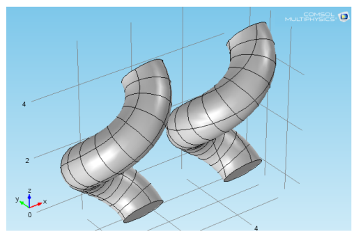
By default, the Twist compensation check box is selected, which prevents the twisting that would otherwise occur due to nonzero torsion for curves that do not belong to a fixed plane. Twist compensation rotates the base circle during the sweep along the helix curve by an amount equal to the integral of the curve torsion.
|
|
Twist compensation affects the position of the vertices on the top side of the helix. Clear the Twist compensation check box to turn it off. See Figure 2-6 below.
|
From the Geometry representation list, select Spline (the default) to represent the helix using splines, or Bézier, to represent the helix using Bézier curves. The difference is that using Bézier curves, the intersections between the surfaces that form the helix are visible edges, whereas they are hidden when using splines.
The value in the Relative tolerance field is a relative tolerance that controls the accuracy of the geometric representation of the helix. The geometric representation is an approximation, which is necessary because it is not possible to exactly represent a helix using NURBS (nonuniform rational basis splines). The default value is 10−4 (or 0.01%).
If you want to make the resulting entities contribute to a cumulative selection, select a cumulative selection from the Contribute to list (the default, None, gives no contribution), or click the New button to create a new cumulative selection (see Cumulative Selections).
Select the Resulting objects selection check box to create predefined selections (for all levels — objects, domains, boundaries, edges, and points — that are applicable) in subsequent nodes in the geometry sequence. To also make all or one of the types of resulting entities (domains, boundaries, edges, and points) that the helix consists of available as selections in all applicable selection lists (in physics and materials settings, for example), choose an option from the Show in physics (Show in instances if in a geometry part) list: All levels, Domain selection, Boundary selection, Edge selection, or Point selection. The default is Domain selection, which is suitable for use with materials and physics defined in domains. For use with a boundary condition, for example, choose Boundary selection. These selections do not appear as separate selection nodes in the model tree. Select Off to not make any selection available outside of the geometry sequence.