Assume that you want to estimate the maximum amount of heat dissipated by a heat sink placed around a resistor for high-power applications. The heat sink consists of an extruded aluminum profile as in Figure 7-8. If the effects at the ends of the elongated heat sink are neglected, the model can be simplified and a decent estimate obtained of the heat dissipated by creating a 2D cross section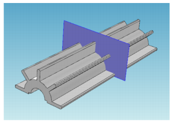 .
.
.|
1
|
Double-click the COMSOL Multiphysics icon to launch COMSOL.
|
|
2
|
The following steps explain how to create two circles to form the core of the heat sink in Figure 7-8. To investigate different dimensions of the heat sink, parameterize the geometry. Start by defining the radius of the outer arc of the heat sink, the radius of the inner arc, and the thickness and the length of the heat sink flanges.
|
|
See Toolbars and Keyboard Shortcuts for links and information about all the available toolbars. Also see The COMSOL Desktop Menus and Toolbars.
It is also useful to review Working with Geometric Entities and Named Selections before continuing with these instructions.
|
|
1
|
|
2
|
In the Parameters table, enter, or copy and paste the values in the table below. The Value column automatically displays the Expression value.
|
|
1
|
|
2
|
|
3
|
|
4
|
|
5
|
|
6
|
A circle with radius R2 displays in the Graphics window. Click the Zoom Extents button ( ) to see both circles.
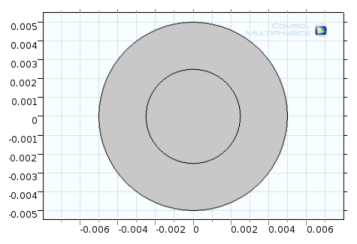
|
1
|
|
2
|
On the Settings window, under Difference, the Active button is On (
|
|
3
|
In the Graphics window, click to select object c1 (the larger circle). c1 is added to the Objects to add list.
|
|
4
|
|
5
|
Select the object c2 (the smaller circle). This can be done by clicking it in the Graphics window. Or open the Selection List window (from the Home toolbar, More Windows>Selection List) and right-click c2 (solid) to Add to Selection.
|
|
6
|
Click the Build Selected button (
 |
|
1
|
|
2
|
|
a
|
|
b
|
|
3
|
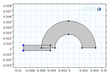
The interaction operation creates the object r1 (not related to the circle radius), which coincides with the intersecting area of the two input objects. 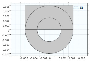
|
4
|
Click the Geometry 1 node. On the Geometry toolbar, from the Booleans and Partitions menu, select Intersection (
|
|
5
|
In the Graphics window click to select each object — dif1 (the combined circle) and r1 (the rectangle).
|
After each click, the object is added to the Input Objects list.
|
6
|
|
1
|
|
2
|
|
a
|
|
b
|
|
3
|
|
4
|
Click the Build Selected button (
|
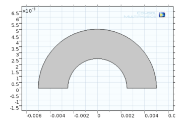
The object r2 (not related to the circle radius) is created. Next, round the sharp edges of the flange by using fillets.
|
1
|
|
2
|
On object r2 (the small rectangle) click each vertex (1 and 4, located in the left-hand corners, highlighted in blue the figure) to add these to the selection lists.
 |
|
3
|
|
4
|
|
1
|
|
2
|
In the Graphics window, click to select object fil1 (the filleted rectangle). It is added to the Input objects list.
|
|
3
|
|
4
|
|
5
|
|
1
|
|
2
|
In the Graphics window click the objects int1, fil1, rot1(1), rot1(2), rot1(3), and rot1(4). These are added to the Input objects section (or click the Select All button (
|
|
3
|
On the Settings window for Union, click to clear the Keep interior boundaries check box to remove the interior boundaries in the union operation. This is good practice if these boundaries do not define separate parts with different materials, for example.
|
|
4
|
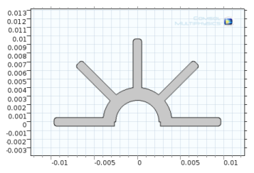
Click the Build All Objects button (
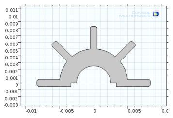 |
Figure 7-9: Final 2D object created in the Model Builder.
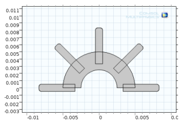
Figure 7-10 shows the geometry sequence used to create Figure 7-9. All primitive objects and the fillet operation are parameterized through the radius of the inner and outer heat sink arcs, the length and thickness of the flanges, and the radius of the fillets. You can change the parameter values in the Parameters table or for any object to create alternative heat sink geometries. The sequence still remains, and when you click the Build All button ( ), a new geometry is created.
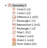
Figure 7-10: An example of a 2D geometry sequence.
|
1
|
|
2
|
On the Settings window under Parameters, enter these settings in the table. Replace the previous data:.
|
|
3
|
|
4
|
Click the Build All button (
 |