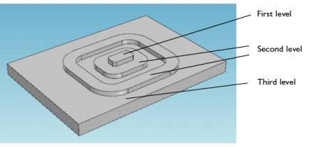
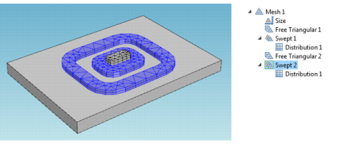
Figure 8-11 shows the 3D Swept mesh for a simple geometry but with a layered structure typical for printed circuit boards or MEMS geometries. In such cases, the swept mesh generation presents an alternative to using a free tetrahedral meshing.
|
|
|
|
1
|
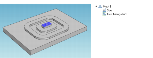
Add a Free Triangular (
|
|
2
|
Add the first level boundary to the selection list (see Figure 8-11 for an example of a suitable geometry).
|
|
3
|
|
4
|
|
6
|
|
7
|
|
8
|
|
9
|
|
10
|
|
11
|
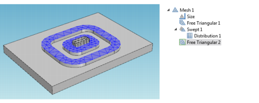
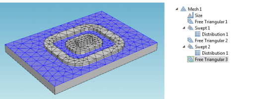
Repeat the same swept operations for the first level domains but now for the second level. Add the second Swept and Distribution nodes.
 |
|
12
|
|
13
|
Mesh the third level domain. Use the Swept mesh operation and enter 4 for the Number of elements in the corresponding Distribution attribute.
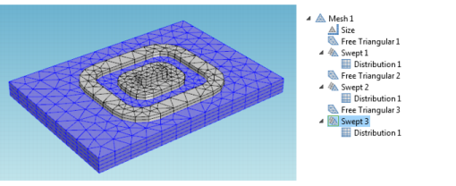 |
The meshing sequence displayed in the Model Builder makes it possible to return to your attribute settings and change mesh sizes and distributions. After making any changes, click the Build All button ( ) or press F8 to rebuild the entire meshing sequence.