Building a COMSOL Multiphysics Model > Building Models in the Model Builder > Structural Mechanics Physics Feature Symbols

Structural Mechanics Physics Feature Symbols
There are physics symbols available with structural mechanics physics features:
Physics Symbols for Boundary Conditions
To display the boundary condition symbols listed in Table 3-5, enable the Show physics symbols from the Graphics and Plot Windows menu on The Preferences Dialog Box. The check box is not selected by default.
These symbols are available with the applicable structural mechanics feature nodes.
1 Requires the Structural Mechanics Module
2 Requires the MEMS Module
About Coordinate Systems and Physics Symbols
Physics symbols connected to a node for which input can be given in different coordinate systems are shown together with a coordinate system symbol. This symbol is either a triad or a single arrow. The triad is shown if data are to be entered using vector components, as for a force. The single arrow is displayed when a scalar value, having an implied direction, is given. An example of the latter case is a pressure.
In both cases, the coordinate directions describe the direction in which a positive value acts. The coordinate direction symbols do not change with the values actually entered for the data.
Physics symbols are in most cases displayed even if no data values have been entered in the node.
In some cases a single feature can display more than one symbol. An example is the Point Load node in the Beam interface, which can display either the Point Force symbol (), the Point Moment symbol (), or both, depending on the data entered. In these cases no symbol is shown until nonzero data is entered.
Displaying Physics Symbols in the Graphics Window — An Example
1
To open the Preferences dialog box:
-
Windows users: From the File menu, select Preferences () You can also customize the Quick Access Toolbar and then click the button.
-
2
Click Graphics and Plot Windows and select the Show physics symbols check box. Click OK.
3
Add a physics interface, for example, Solid Mechanics, from the Structural Mechanics branch.
4
Add any of the feature nodes listed in Table 3-5 to the physics interface. Availability is based on license and physics interface.
5
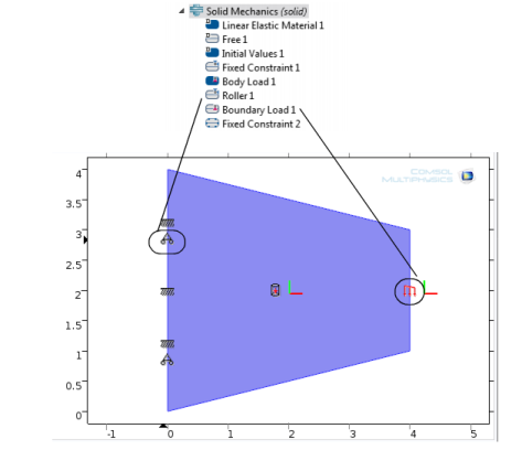
When adding the boundary, edge, or point (a geometric entity) to the Selection list in the feature Settings window, the symbol displays in the Graphics window. See Figure 3-9.
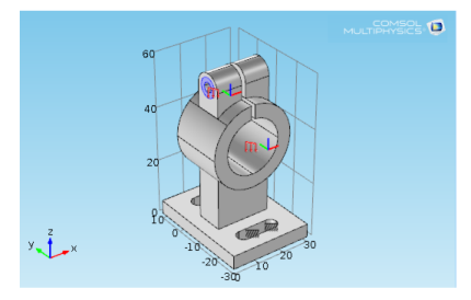
Figure 3-9: Example of Boundary Load physics symbols as displayed in the COMSOL Multiphysics model “Deformation of a Feeder Clamp.”
6
Figure 3-10: Example of Roller and Boundary Load physics symbols as displayed in the COMSOL Multiphysics model “Tapered Cantilever.”