Throughout COMSOL Multiphysics there are many lists of selected geometric entities, all based on the same principle — pick a domain, boundary, edge, or point and use methods to add or remove these geometric entities to create selections that define, for example, the parts of the geometry where a material or boundary condition is active. Such lists appear in Settings windows for defining equations and material properties, boundary conditions, sources, and other parts of the model’s design, or the Variables node ( ) definitions for variables that are not defined in the entire model.
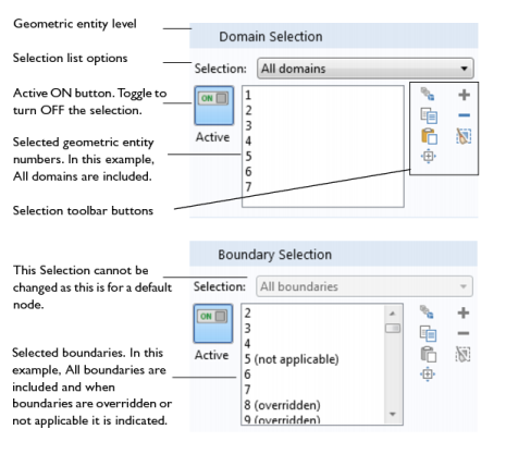
All levels of geometry can be treated individually. You can add and remove 3D geometric entities (domains, boundaries, edges, or points) to selection lists in different ways, including buttons on the Graphics toolbar (The Graphics Window Toolbar Buttons), using The Selection List Window, clicking directly on the geometry, or clicking buttons in the Settings window. You can also select entities in the list to then remove them from the selection, for example. Ctrl+A selects all entities in the list. Table 6-2 lists the buttons that display on every Settings window with a geometric entity selection list as displayed in Figure 6-6.
In The Graphics Window, the geometric entities are color highlighted as you make the selections, and you can lock the selections by turning off the active selection (at most one selection can be active at a time) or click the Select Node button ( in 3D) in the Graphics window toolbar.
The name of the section where the list of selected geometric entities is managed depends on the geometric entity level. For example, Figure 6-6 displays a Domain Selection section.
Every geometric entity selection section also has an Active button to toggle between turning ON  and OFF
  selections for that node.
For physics nodes that are default nodes (see Physics Interface Default Nodes) the selection defaults to all geometric entities on the applicable level (all domains or all boundaries, for example, in Figure 6-6), and the Selection list is not active. You can add other nodes that override the default nodes for some or all entities. Those entities are then marked (overridden) in the selection list for the default node.
|
•
|
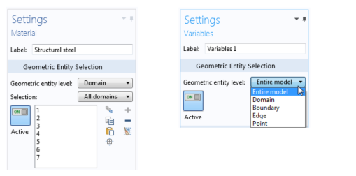
Geometric Entity Selection: For Materials and Variables nodes, where you first select the level (domain, boundary, and so on), from a Geometric entity level list. See Figure 6-7 for an example using the “Diagonal Mounting Detail of a Communication Mast” model.
|
|
•
|
Domain Selection: For nodes that define, for example, material models, sources, and body loads in domains. See Figure 6-6 for an example.
|
|
•
|
Boundary Selection: For nodes that define, for example, boundary conditions.
|
|
•
|
Edge Selection: For nodes that define, for example, conditions and forces on edges. This is applicable to 3D models only.
|
|
•
|
Point Selection: For nodes that define, for example, point sources and point loads.
|
From the Selection list you can choose one of the following options:
|
•
|
Manual (the default): Select the geometric entities directly in the Graphics window, using The Selection List Window, or using the Paste Selection button. See below for more information about those selection methods.
|
|
|
If you start by setting the Geometric entity level to Domain, and then select All domains, the Selection list displays all domains. If you make any changes to this list (for example, remove a domain) the Selection list reverts to Manual.
|
|
•
|
All domains, All boundaries, All edges, All points: Depending on the geometric entity level, you can choose one of these options to select all entities. See Figure 6-6 for example.
|
|
•
|
Defined named selections: Selection nodes added in the geometry sequence or under Definitions (as well as selections created from Boolean operations, for example) are available in the Selection lists for nodes that define model properties for the same geometric entity level. You can rename such selection nodes to better reflect what the selected entities represent. A named selection can consist of, for example, the domains where a volume force acts, the boundaries where an inflow occurs, or points that are grounded. Named selections are useful for reusing selections in a model component and to clearly indicate what parts of geometry that the selected entities include or represent. See Creating Named Selections.
|
In the lists of selected entities, (overridden) and (not applicable) can display next to the label (the number) of a selected entity. See Figure 6-6 and Physics Node Status for more information about these status indicators. There is also an Override and Contribution section in all physics nodes. It provides an overview of how the physics nodes and their selections interact. See Physics Exclusive and Contributing Node Types.
If the geometry is an assembly you have access to specific pair conditions (typically on boundaries) that you choose from a Pairs submenu on the main physics nodes’ context menus. In the Settings window for such pair nodes, a Pair Selection section contains a list of the applicable pairs (typically identity pairs). The Boundary Selection section (or another standard selection section) is then not possible to modify and shows the entity numbers for the boundaries, for example, that the selected pairs include. Select one or more pairs from the Pairs list to specify where to apply the pair condition. See Identity and Contact Pairs.
|
|