Use the Selection List window ( ) (see Figure 6-8) to make it easier to choose objects, for example, while working with complex geometries and when you need to easily locate a geometric entity that is not easily viewed. The Selection List is particularly useful when you know the geometric entity number to select; for example, when you are following step-by-step instructions to build an example from the application libraries (in that case you can also copy and paste the selections directly from the instructions).
|
|
|
|
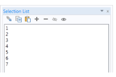
Figure 6-8: The Selection List window and toolbar. Most of the toolbar buttons are also on a node Settings windows. In this example, the numerical representation for the domains is listed. See Table 6-2 for button information.
The Selection List window displays all geometric entities of a certain type (boundaries, for example). COMSOL Multiphysics determines the geometric entities listed based on where in the model you are working. This is different from selection lists in Settings windows, which contain lists of the selected entities only (see About Selecting Geometric Entities, Figure 6-6).
Click any item to see it highlighted in The Graphics Window — except if the item is hidden, which is indicated in the Selection List by (hidden) — and select items as described in Selecting and Clearing Selection of Geometric Entities. For example, use the Selection List in these situations:
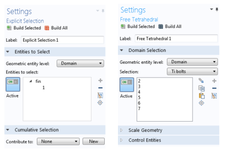
When working in windows with Selection or Geometric scope sections (a Selection window under a Definitions node for example), or anywhere you assign materials, physics features, boundary conditions, and other Component settings. The Selection List displays the specific geometric entity level selected (domain, boundary, edge, or point). See Figure 6-13 for an example.
When in the Model Builder under the Geometry node, the geometry objects are displayed in the Entities to select, for example, ext1 (extrusion), blk1 (solid), or cone1 (solid) (Figure 6-9). You might also use it with a Chamfer or Fillet geometry feature when you want to locate specific points. To specify the selection level, click the Select Points button in the Graphics toolbar and add the points to the Vertices to fillet or Vertices to chamfer lists. See Creating Named Selections in the Geometry Sequence for details about creating selections based on geometry sequences.
When in the Model Builder under the Mesh node, the list also includes information on which entities are meshed by adding (meshed) to the right of the meshed entities. If the Geometry has Mesh Construction entities, the list also specifies if a construction entity has been removed; see Mesh Control Entities. This is indicated next to the entity in the list by (meshed and removed).
|
|