You can create selection nodes under the Component node’s Definitions node to represent various parts of the geometry and simplify the process of assigning materials, model equations, boundary conditions, and other model properties. These user-defined selections can be reused during modeling and named using descriptive titles — for example, Tube, Wall, or Fluid. Changes to the selection (for example, by adding or removing a boundary) updates all nodes in the Component that use that particular selection.
Use the buttons listed in Table 6-2 to create, copy, and paste selections. When there is the possibility of overlapping geometric entities, it is recommended that you use The Selection List Window to ensure the correct part of the geometry is selected.
There are different types of selections: Explicit selections, selections by enclosing part of the geometry by a bounding Ball, Box, or Cylinder, Boolean selections (Union, Intersection, Difference, and Complement), and selections of Adjacent geometric entities. To add selection nodes, right-click a Definitions node and choose from the Selections options as listed in Table 6-6.
You can also right-click the Geometry node and choose from Selections options similar to those in Table 6-6 for defining selections based on the geometry objects in the geometry sequence. See Creating Named Selections in the Geometry Sequence.
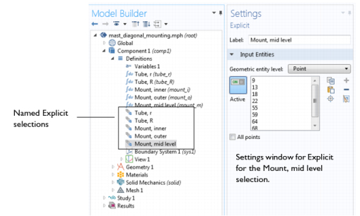
Figure 6-13 uses a COMSOL Multiphysics Applications Libraries example, which includes several user-defined selections.
|
2
|
Navigate to the COMSOL Multiphysics>Structural Mechanics>mast_diagonal_mounting model file. Double-click to open it.
|
|
3
|
Expand the Definitions node under Component 1. Several nodes display in the Model Builder. Click the nodes shown in Figure 6-13 to examine the list of geometric entities displayed in the Settings window for Explicit.
|
|
|
In the selection Settings windows, also click the Zoom to Selection (
|
|
|
||
|
|
||
|
|
||
|
|
||
|
|
Use an Explicit node to create the selection using the normal selection tools for individual geometric entities (boundaries, for example) on the geometric entity level chosen.
|
|
|
|
||
|
|
||
|
|
||
|
|
||
|
|