|
2
|
From the File menu (Windows) or the Options menu (the cross-platform version), choose Preferences. In the Preferences dialog box, select Physics Builder in the list and then select the Enable Physics Builder check box if not selected already.
|
|
3
|
From the File menu, choose New (
|
|
4
|
On the Home toolbar, click Add Physics Interface (
|
|
5
|
|
-
|
In the Description field enter Thermoelectric Effect. Click the Rename node using this text button (
|
|
-
|
|
-
|
|
-
|
If you have a custom Icon for the interface, click the Browse button to locate the icon file. The default is to use the physics.png icon (
|
|
6
|
The Thermoelectric Effect interface should support all space dimensions except 0D, so under Restrictions, leave the Allowed space dimensions list with the default contents, which includes all space dimensions except 0D.
|
|
7
|
Under Restrictions in the Allowed study types list, select the default Time Dependent study type and click the Delete button (
|
|
8
|
In the Settings section, verify that Domain is selected in the Top geometric entity level list. This means that the equations in the physics interface apply to the domains in the geometry, which is the case for most physics interfaces. Leave the setting in the Default frame list at the default value (Material).
|
|
9
|
It is good practice to save the physics interface after completing some steps. From the File menu, choose Save and create a physics builder file, ThermoelectricEffect.mphphb in the default location. Click Save.
|
|
1
|
On the Physics Interface toolbar click Dependent Variable Declaration (
|
|
2
|
|
-
|
|
-
|
From the Physical quantity list select Temperature (K), which makes suitable default values appear for the variable name and description.
|
|
-
|
|
-
|
|
3
|
Keep the default Preferences settings that make the dependent variable available for plotting (Show in plot menu) and for use as an input in other physics interfaces (Announce variable to feature inputs).
|
|
4
|
Keep the default Discretization settings (for default second-order Lagrange elements).
|
|
5
|
|
6
|
|
-
|
|
-
|
From the Physical quantity list select Electric potential (V), which makes suitable default values appear for the variable name and description.
|
|
-
|
|
-
|
|
7
|
|
1
|
|
2
|
|
-
|
In the Description field enter Heat transfer model. Click the Rename node using this text button (
|
|
-
|
|
-
|
|
3
|
Under Restrictions keep the default setting Same as parent for both the Allowed space dimensions and Allow study types lists. If you select Customized you can restrict the feature to a subset of the allowed space dimensions or study types for the physics interface.
|
|
4
|
Keep the default values for the rest of the sections for the Heat Transfer Model node.
|
|
5
|
Right-click the Heat Transfer Model node and from the Variables menu select Dependent Variable Definition (
|
|
6
|
In the Settings window locate the Definition section. From the Physical quantity list select Temperature (K).
|
|
7
|
Keep the default settings for the rest of the Dependent Variable Definition node.
|
|
8
|
|
9
|
|
-
|
|
-
|
|
-
|
|
-
|
|
-
|
Keep the default settings for the Array type (Single) and Dimension (Scalar) lists for a basic scalar quantity. Also keep the default Allowed values to Any for an entry of a general scalar number.
|
|
-
|
|
10
|
Keep all other default values for the User Input node.
|
|
11
|
Right-click the User Input node and select Variable Definition (
|
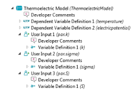
This user input then declares a variable with the name k and the expression par.k, which evaluates to the value entered for the user input. You can also refer to k directly in the weak form equation. A user of this physics interface refers to this variable as tee.k in the predefined expressions for results evaluation, for example.
|
12
|
Keep all other default values for the Variable Definition subnode.
|
|
13
|
Right-click the Heat Transfer Model node and from the Equations menu select Weak Form Equation (
|
This adds a Weak Form Equation node where you specify an equation for the domains in the physics interface.
|
14
|
In the Settings window, locate the Integrand section. In the Expression field enter -k·∇Τ·test(∇T). This expression implements the heat equation formulation for this interface.
|
Press Ctrl+Space to get a list of the supported operations that includes any special characters. See Tensor Parser for the keyboard entries to create the del operator (∇) and the dot product (·).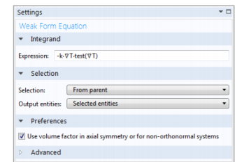
|
15
|
Keep all other default values for the Weak Form Equation node.
|
|
1
|
|
2
|
|
-
|
In the Description field enter Thermoelectric model. Click the Rename node using this text button (
|
|
-
|
|
-
|
|
3
|
In the Preferences section select the Add as default feature check box. Keep the setting in the Default entity types list to make this a default physics model in all domains.
|
|
4
|
Keep the rest of the settings for the Thermoelectric Model.
|
|
5
|
Right-click the Thermoelectric Model node and from the Variables menu select Dependent Variable Definition (
|
|
6
|
In the Settings window locate the Definition section. From the Physical quantity list select Temperature (K). Keep the other default settings.
|
|
7
|
Right-click the Thermoelectric Model node and from the Variables menu select Dependent Variable Definition (
|
|
8
|
In the Settings window locate the Definition section. From the Physical quantity list select Electric potential (V). Keep the other default settings.
|
|
1
|
|
2
|
|
-
|
|
-
|
|
-
|
|
-
|
|
-
|
Keep the default settings in the Array type (Single) and Dimension (Scalar) lists for a basic scalar quantity. Also leave the Allowed values setting to Any for an entry of a general scalar number.
|
|
-
|
|
3
|
Keep all other default settings for the User Input 1 node.
|
|
4
|
You can then refer to k directly in the weak form equation. A user of this interface refers to this variable as tee.k in the predefined expressions for results evaluation, for example.
|
5
|
Keep all other default settings for the Variable Definition subnode.
|
|
6
|
|
7
|
|
-
|
|
-
|
|
-
|
|
-
|
|
-
|
Keep the default settings in the Array type (Single) and Dimension (Scalar) lists for a basic scalar quantity. Also leave the Allowed values setting to Any for an entry of a general scalar number.
|
|
-
|
|
8
|
Keep all other default settings for the User Input 2 node.
|
|
9
|
You can then refer to sigma directly in the weak form equation. A user of this interface refers to this variable as tee.sigma in the predefined expressions for results evaluation, for example.
|
10
|
Keep all other default settings for the Variable Definition subnode.
|
|
11
|
|
12
|
|
-
|
|
-
|
|
-
|
|
-
|
|
-
|
Keep the default settings in the Array type (Single) and Dimension (Scalar) lists for a basic scalar quantity. Also leave the Allowed values setting to Any for an entry of a general scalar number.
|
|
-
|
|
13
|
Keep all other default settings for the User Input 3 node.
|
|
14
|
You can then refer to S directly in the weak form equation. A user of this interface refers to this variable as tee.S in the predefined expressions for results evaluation, for example.
|
15
|
Keep all other default settings for the Variable Definition subnode.
|
|
1
|
Right-click the Thermoelectric Model node and from the Variables menu select Variable Declaration (
|
|
2
|
|
-
|
|
-
|
|
-
|
|
-
|
|
-
|
|
3
|
|
4
|
Press Ctrl+Space to get a list of the supported operations that includes any special characters. See Tensor Parser for the keyboard entries to create the del operator (∇) and the dot product (·).
|
5
|
Keep all other default settings for the Variable Definition 1 subnode.
|
|
6
|
Right-click the Thermoelectric Model node and from the Variables menu select Variable Declaration (
|
|
7
|
|
-
|
|
-
|
|
-
|
|
-
|
|
-
|
|
8
|
|
9
|
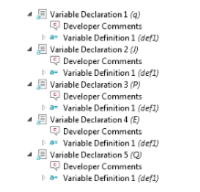
In the Settings window locate the Definition section. In the Expression field, enter -sigma·(∇V+S*∇T). Keep all other default settings for the Variable Definition 1 subnode.
|
|
10
|
Right-click the Thermoelectric Model node and from the Variables menu select Variable Declaration (
|
|
11
|
|
-
|
|
-
|
|
-
|
|
-
|
|
-
|
|
12
|
|
13
|
In the Settings window locate the Definition section. In the Expression field enter S*T. Keep all other default settings for the Variable Definition 1 subnode.
|
|
14
|
Right-click the Thermoelectric Model node and from the Variables menu select Variable Declaration (
|
|
15
|
|
-
|
|
-
|
|
-
|
|
-
|
|
-
|
|
16
|
|
17
|
In the Settings window locate the Definition section. In the Expression field enter −∇V. Keep all other default settings for the Variable Definition 1 subnode.
|
|
18
|
Right-click the Thermoelectric Model node and from the Variables menu select Variable Declaration (
|
|
19
|
|
-
|
|
-
|
|
-
|
|
-
|
|
-
|
|
20
|
|
21
|
In the Settings window locate the Definition section. In the Expression field, enter J·E. Keep all other default settings for the Variable Definition 1 subnode.
|
|
1
|
Right-click the Thermoelectric Model node and from the Equations menu select Weak Form Equation (
|
|
2
|
In the Settings window locate the Integrand section. In the Expression field, enter q·test(∇T)+Q*test(T). Press Ctrl+Space to enter the del operator (∇) and the dot product (·).
|
|
3
|
|
4
|
In the Settings window, locate the Integrand section. In the Expression field, enter -J·test(E). Note that -E is used instead of ∇V. Either syntax would work.
|
|
1
|
|
2
|
|
3
|
|
4
|
|
5
|
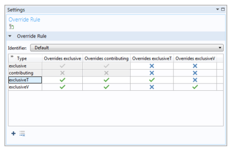
Click to set the Overrides exclusive and Overrides contributing columns for exclusiveT and exclusiveV to a green check mark.
|
|
6
|
|
7
|
Click in column Overrides exclusiveV across from exclusiveV to set to a green check mark. The Settings window should match the figure.
 |
|
1
|
|
2
|
|
-
|
In the Description field enter Temperature. Click the Rename node using this text button (
|
|
-
|
|
-
|
|
3
|
In the Restrictions section, keep the default setting (Same as parent) for the Allowed space dimensions and Allow study types lists.
|
|
4
|
|
-
|
Click the Add button
|
|
-
|
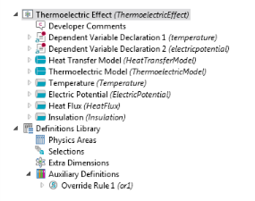
From the Override rule list choose Locally defined. Keep the default Override Rule 1 in the Link list.
|
|
-
|
|
1
|
|
2
|
|
-
|
|
-
|
|
-
|
|
-
|
|
-
|
Keep the default settings in the Array type (Single) and Dimension (Scalar) lists for a basic scalar quantity. Also leave the Allowed values setting to Any for an entry of a general scalar number.
|
|
-
|
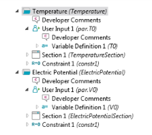
In the Default value field enter 293.15[K] corresponding to a room temperature of 20 degrees Celsius.
|
|
3
|
Keep all other defaults for the User Input 1 node.
|
|
4
|
You can then refer to T0 directly in the constraint equation. A user of this interface refers to this variable as tee.T0 in the predefined expressions for results evaluation, for example.
|
5
|
Now define a section in the Settings window for the boundary condition:
|
6
|
|
7
|
|
-
|
|
-
|
|
-
|
Click the Add (
|
|
8
|
Right-click the Temperature node and from the Equations menu select Constraint (
|
|
9
|
In the Settings window locate the Declaration section. In the Expression field enter T0-T to make the temperature T equal to T0 on the boundary (the constraint makes the expression equal to zero).
|
|
10
|
|
11
|
Keep all other default values for the Constraint 1 node.
|
|
1
|
|
2
|
|
-
|
In the Description field enter ElectricPotential. Click the Rename node using this text button (
|
|
-
|
|
-
|
|
3
|
In the Selection Settings section:
|
|
-
|
From the Override rule list choose Locally defined. Keep the default Override Rule 1 in the Link list.
|
|
-
|
|
4
|
|
5
|
|
-
|
|
-
|
|
-
|
|
-
|
|
-
|
Keep the default settings in the Array type (Single) and Dimension (Scalar) lists for a basic scalar quantity. Also leave the Allowed values setting to Any for an entry of a general scalar number.
|
|
-
|
|
6
|
Keep all other defaults for the User Input 1 node.
|
|
7
|
You can then refer to V0 directly in the constraint equation. A user of this interface refers to this variable as tee.V0 in the predefined expressions for results evaluation, for example.
|
8
|
Keep all other defaults for the Variable Definition 1 subnode.
|
Now define a section in the Settings window for the boundary condition:
|
9
|
|
10
|
|
-
|
|
-
|
|
-
|
Click the Add (
|
|
11
|
|
12
|
In the Settings window locate the Declaration section. In the Expression field, enter V0-V, which constrains the value of the potential V to V0.
|
|
13
|
Locate the Shape Declaration section and from the Physical quantity list select Electric potential (V).
|
|
1
|
|
2
|
|
-
|
In the Description field enter Heat flux. Click the Rename node using this text button (
|
|
-
|
|
-
|
|
3
|
In the Selection Settings section from the Override type list choose Contributing (that is, more than one heat flux can contribute to the total heat flux across a boundary).
|
|
4
|
|
5
|
|
-
|
|
-
|
|
-
|
|
-
|
|
-
|
Keep the default settings in the Array type (Single) and Dimension (Scalar) lists for a basic scalar quantity. Also leave the Allowed values setting to Any for an entry of a general scalar number.
|
|
-
|
|
6
|
You can then refer to qin directly in the weak form equation. A user of this interface refers to this variable as tee.qin in the predefined expressions for results evaluation, for example.
|
7
|
Leave all other default settings for the Variable Definition 1 subnode.
|
Now define a section in the Settings window for the boundary condition:
|
8
|
|
9
|
|
-
|
|
-
|
|
-
|
Click the Add (
|
|
10
|
|
11
|
In the Settings window locate the Integrand section. In the Expression field, enter qin*test(T). For a theoretical explanation of this expression, see the earlier theory section.
|
|
1
|
|
2
|
|
-
|
In the Description field enter Insulation. Click the Rename node using this text button (
|
|
-
|
|
-
|
|
3
|
|
4
|
In the Preferences section, select the Add as default feature check box. Keep the default setting in the Default entity types list to make this a default boundary condition on Exterior boundaries only.
|
|
1
|
|
2
|
|
3
|
|
4
|
|
-
|
|
-
|
|
-
|
|
6
|
Right-click the Surface (
|
|
7
|
|
8
|
|
-
|
|
-
|
In the Description field enter Temperature. This makes temperature the default for all scalar plots.
|
|
1
|
|
2
|
In the Settings window for Physics Area under Parent Area, expand the Root>Heat Transfer folder (
|
|
3
|
In the Physics Area Settings section:
|
|
-
|
|
-
|
|
-
|
The default Icon is physics.png (
|
|
-
|
In the Weight field enter 10 to make the Thermoelectric Devices area appear last in the list under Heat Transfer (the higher the weight, the lower position the physics area gets in the tree of physics interfaces).
|
|
4
|
Click the Thermoelectric Effect node. In the Settings window for Physics Interface, expand the Physics Area section.
|
|
5
|
Expand the Heat Transfer folder. Right-click Thermoelectric Devices (
|
|
6
|
Save the file that contains the physics interface as ThermoelectricEffect.mphphb.
|
This completes the definition of the Thermoelectric Effect interface. The next section tests the physics interface.