Define a Base Vector System ( ) using a set of base vectors to form a coordinate system. The system does not necessarily need to be orthonormal, but when it is, declaring it orthonormal and linear enables simplifications that improve performance.
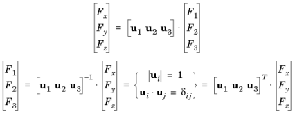
A vector F is represented by its contravariant components [F1, F2, F3]T in the base of the new base vector system defined by the base vectors u1, u2, and u3 on the form F = F1u1 + F2u2 + F3u3. Expressing the base vectors as components in another system (for example, the global spatial system [ex, ey, ez]) gives the transformation matrix between bases:
|
|
The Curvilinear Coordinates interface can create special base vector systems in Curvilinear System nodes (
|
In the Coordinate names table, the default names are entered—x1, x2, and x3. In planar 2D models, x1 and x2 are typically the in-plane coordinates, and x3 is the out-of-plane coordinate. Note that these coordinate names are only used as indices for vector and tensor variable names, and cannot be evaluated as variables. The labels for each coordinate name—First, Second, and Third—include the default name in parentheses.
Define the Base vectors in terms of the global Cartesian coordinates (typically x, y, and z); one base vector on each row (two for 2D and three for 3D).
|
|
For 1D models, select which basis vector is parallel to the 1D geometry. Select an option from the In-plane index list. The default is 1.
|
|
|
For 2D models, select which basis vector to compute as the cross product of the two in-plane vectors specified. Select an option from the Out-of-plane index list. The defaults are 3 for a plane 2D model and 2 for an axisymmetric 2D model. For example, to map the first vector, x1, to the direction defined by y = x in 2D, enter 1 in the fields under x and y on the x1 row.
|
Set base vector system properties that help simplify the coordinate transformations. Select the Assume orthonormal check box if the coordinate system is orthonormal.
|
|
Go to Name for information about the Settings window Label and Name. Also see Settings and Properties Windows for Features Nodes.
|
|
|
|