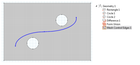
Figure 8-12 shows a 2D geometry with two holes and a Bézier Polygon that is intended not to be a part of the model but is included only to control mesh size inside the domain. This example is about Mesh Control Entities and uses a simple geometry.
|
1
|
Add a Mesh Control Edges (
|
|
2
|
|
3
|
|
4
|
Add a Free Triangular (
|
|
5
|
|
7
|
|
8
|
Click the Build All button (
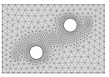 |
Figure 8-13: Fine mesh inside the domain.
|
•
|
If you have the CFD Module, see Turbulent Flow Over a Backward Facing Step: Application Library path CFD_Module/Single-Phase_Benchmarks/turbulent_backstep.
|
|
•
|
If you have the Heat Transfer Module, see Turbulent Flow Over a Backward Facing Step: Application Library path Heat_Transfer_Module/Verification_Examples/turbulent_backstep.
|
|
•
|
If you have the Batteries & Fuel Cells Module, see Thermal Modeling of a Cylindrical Lithium-ion Battery in 3D: Application Library path Batteries_and_Fuel_Cells_Module/Thermal_Management/li_battery_thermal_3d.
|
|
•
|
If you have the CFD Module, see Airflow Over an Ahmed Body: Application Library path CFD_Module/Single-Phase_Benchmarks/ahmed_body.
|